New posts will appear here:
Interactive programming environments
When I read the latest post in the programming in the twenty-first century blog, a blog I have been reading for years, I felt I should finally update this blog at least with a screenshot of the interactive programming environment I've been working on (and in) recently.

Here are some videos:
James Hague has written about the interactive environments that existed on old computers before, but his latest post blew my nostalgia into overdrive, compelling me to post this. Thanks James. Thames.
Fluid Concepts and Creative Analogies
The book Fluid Concepts and Creative Analogies describes a cognitive model that is very compelling and fun to study.
When you run an implementation of this cognitive model, the cognitive model seems
to actively pursue an agenda in an incredible, human like way. Some aspects of its behaviour are reminiscent of ant colony simulators, with codelets as the ants. Each codelet is attracted to a "salient" ("pheromone scented") part of the workspace and
does one little piece of work - proposing or building a structure,
changing the salience of a new part of the workspace, changing the
activation and slippability of one of the concepts in the slipnet, and
so on. As the codelets run, the system seems to be pursuing an agenda, an agenda that is different every time it runs, and that is emergent rather than explicitly programmed in.
Trying to apply this cognitive model to other domains is a mind bending exercise. By way of contrast, when applying a genetic algorithm to a problem for example, you just need to define a few recombination operators for generating new proposed solutions from old ones, and a fitness function for measuring a proposed solution. When this program runs, its style is simply a parallel prioritized search. The fluid concepts cognitive model on the other hand has a much more compelling, beautiful style as it works toward a solution. Whether it is more or less efficient is not as important to me as its behaviour.
When applying this cognitive model to a new domain, you need examine the domain in more detail than with other AI techniques. You need to choose the concepts
involved, how they are connected to each other and how these concepts manifest themselves through the
"top-down" codelets they can generate and how "bottom-up" codelets
should be influenced by the activations of the concepts. When you see this program running, you see a story unfold about a thought process rather than just a dry search. The system notices features, which may activate concepts, which may direct the system to search for features related to that activated concept. The activation of a concept may also strengthen the bond between two other concepts, causing a slippage of activation. For example, thinking about the letter "a" and the concept of successorship may lead you to start thinking about the letter "b". Its this richness and depth of domain knowledge that gives systems based on this cognitive model such a compelling, beautiful character.
As well as Fluid Concepts and Creative Analogies, I've been reading the following two books written by the co-authors:
Analogy-Making as Perception - A Computer Model by Melanie Mitchell
The Subtlety of Sameness by Robert French
Also its helpful when studying this to read An evaluation of the Fluid Concept Architecture, a good examination of the cognitive model.
Links:
The book
A review and description of the book by Daniel Dennett
Fluid Analogies Research Group
A java implementation of Copycat by Scott Bolland.
Update: Scott Bolland appears to have disappeared from the internet. A copy of the Copycat program along with the tutorial pages appears on the Internet Archive.
Synthbench v002

tech notes:
Synthbench is an audio synthesis tool inspired by the "Reactable" instrument.
It features:
- Generators and LFO controllers with waveforms editable in real time
either interactively with the mouse or through lua commands.
- Generators and LFO controllers that use standard waveforms.
- High pass, low pass and band pass filter effect nodes
- Delay / phase shift effect node
- A tracker, accessible using tracker controller nodes that can be
attached to a generator like any other controller node
- The two parameters of a generator node can be separately controlled by
a controller node
interface notes:
To adjust the tempo, the center node (small purple circle) needs to be
selected and the controls window needs to be visible ("Controls" menu
item toggles it).
The "mf" and "ma" controller nodes need to be attached to a generator
to enable it to be controlled by the tracker. Sliding the "Track"
parameter selects which track controls the controller node.
If you find that a controller node is controlling the pitch instead of
the amplitude or vice versa, try moving the controller around the
generator until what it controls changes.
When placing a high or low pass filter, you may want to increase the Q
parameter slightly to make the effect more dramatic.
The generator and controller nodes that allow you to modify the
waveform are the "lua" nodes. The "WaveformEdit" menu item toggles the
waveform editor.
The "Waveform", "Tracker" and "Synthbench" menu items toggles the
visibility of the respective panes.
Download
The Cave - fugue @ Syntax 2011

This demo uses an engine similar to wtf-atabimp, with a few new features, such as high speed OpenGL rendered voxels and a clean up of the mp3 playing code. All voxel operations (such as "adding" and "carving out" voxels) are done in constant time, with the "housekeeping" of the voxel render list occuring at render time.
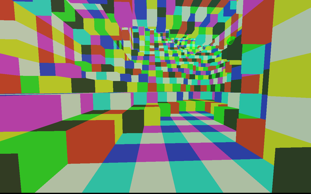
This demo is built on a framework that allows the entire demo to be driven by lua. The lua files are included, and can be modified freely. There is also a console available from the demo itself, providing a "live coding" environment which permits complete modification of the demo while it is running. There is an unmarked pane splitter at the bottom of the window which can be moved to reveal the console. The console now maintains a persistent session, so the command history is maintained between runs.
Thanks to cTrix for his wizardry in creating this awesome music for the demo!
Download
WikiReader Forth Simulator - update
Now features:
- Stack window refreshes after every command
- WikiReader style boot menu
- New sample programs
- Added SP@ word
- WikiReader consistent implementation of PICK
- Found and fixed a memory corrupting crash bug in Ficl Forth associated with the LOCALS| word. WikiReader Forth doesn't support LOCALS| so this is moot.
- Includes a scroller sample which doesn't use LOCALS| or PICK
Nokia E71 live coding - update
This update features:
- Single application instead of 2 separate applications
- Full use of E71 keyboard - all characters accessible using bottom left meta key, no need to use Nokia special character dialog
- Tested on the Nokia C5
- Trace window with go to error capability
- Console with history and persistent session
- Saving and loading console sessions
- Integrated editor with go to line and search functions
- Editor and Console use fixed width font
- Several sample programs included with installation
Lua based live coding tools for the Nokia E71


Installing
Using Nokia PC Suite, install the following .sis files:
- qt.sis
- LiveCode.sis
- TextEd.sis
- spectrum.sis
They can be installed in any order.
After installing, its handy to map the hardware buttons mapped so they start LiveCode, TextEd and spectrum to save you from having to traverse the menu every time you want to make a change to your lua code or see the effect of your change.
Running the tools
LiveCode and TextEd together provides a basic and fun live coding environment for Nokia mobile phones. When you run LiveCode, it loads a file called livecode.lua in the Root directory of the phone memory to retrieve the newest definitions of the update and render functions. Running the TextEd program after this will open livecode.lua for editing in a basic text editor, where any lua code may be written and update and render can be redefined. After making your changes and saving, you can return to the running instance of LiveCode, and reload your definitions of update and render by hitting any key on your phone.
I've included a small set of samples to get you started. Place them in the Root directory of the phone memory, rename one of them to livecode.lua then start the LiveCode program to try it out! If you read the samples, you'll see the only callback currently defined is drawLine, which takes 4 numbers to specify the endpoints of the line to be drawn. This function can only be called inside render.


Audio coding with spectrum and lua
I have also provided a version of the spectrum demo with a slight modification - this version allows the waveform to be specified from lua. The spectrum program reloads the file spectrum.lua whenever the mode settings are changed to obtain the newest definition of the calcsample function, which it uses to compute the waveform. If you open TextEd after opening spectrum, TextEd will allow you to edit the spectrum.lua file. Starting the LiveCode program will tell TextEd to go back to editing livecode.lua the next time it starts.
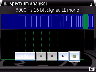


The original version of the spectrum demo comes from the Qt SDK, available from qt.nokia.com
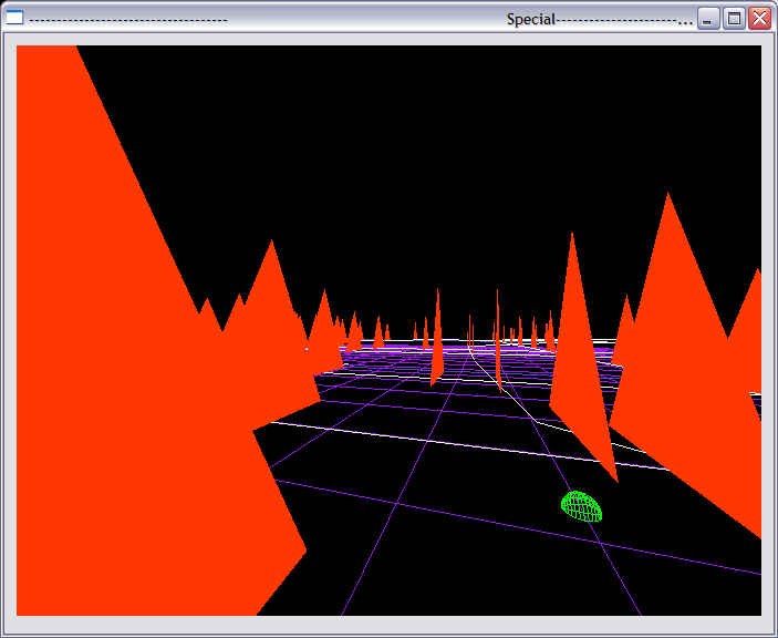
wtf-atabimp - fugue @ Flashback 2011
Download
This demo is built on a framework that allows the entire demo to be driven by lua. The lua files are included, and can be modified freely. There is also a console available from the demo itself, providing a "live coding" environment which permits complete modification of the demo while it is running. There is an unmarked pane splitter at the bottom of the window which can be moved to reveal the console.
This is my first demo, and I wrote it this way to permit the protoyping of different effects easily. In this demo, there are only 3 effects:
- A 3D braitenberg vehicle simulation, where 200 randomly placed objects self organize into a group of 3D curves
- An animated heightmap
- A randomly generated group of polylines with a bunch of triangular guys moving along them.
Synthbench - Flashback update
I presented this version at Flashback 2011. It features:
- Generator and controller elements that use lua specified waveforms
- A continuously running tracker where instruments can be assigned to the tracks using "music" effect elements
- Completely scriptable operation. From the lua console it is possible to construct the table, and manipulate all its controls including the data in the tracker or the waveforms in the lua generators and controllers over time.
- Update callbacks which are called at 20Hz, and also after each note played by the tracker
- The delay effect now mixes the input with a delayed version of itself
- There are also 3 filter effects - band pass, high pass and low pass filters
There are some example scripts which demonstrate how to use the scripting features. You can also refer to the readme file for further documentation.
WikiReader Forth Simulator

I bought a WikiReader recently, which apart from being a 4GB text only offline version of Wikipedia, comes with a fun feature where it can run any Forth programs which are placed on its internal mini SD card. I wrote this program so I could test my small Forth programs without having to swap the mini SD card in and out repeatedly. The current version can run most of the test programs exactly as they appear on the SD card very faithfully. This app uses a Forth interpreter provided by the open source embeddable Forth implementation FICL (http://ficl.sourceforge.net/), and it works by providing device specific words as callbacks to a simulated WikiReader. It implements enough now to be useful, including the framebuffer functions, GDI functions (including text rendering using the device's font) and input functions, so I'm releasing it.
Usage:
See simlib.4th for the list of device specific words supported by this simulator, as well as simtest.4th for some simple examples. The other Forth programs included are the ones which come with the device and which I've tested on this simulator. Please refer to them for more reference material when writing your own programs.
The console supports multi-line commands. To enter a multi-line command, press ctrl-enter for a new line. The console also keeps a history of all commands entered. To navigate the history, press ctrl-up or ctrl-down. Pressing up or down without ctrl will move the cursor around the console.
To simulate moving your finger over the screen during the execution of your Forth command or program, move your mouse over the screen while holding down the left mouse button. To simulate hardware key presses, the hardware keys are mapped as follows:
| Search | Q |
| History | W |
| Random | E |
A note about the calculator progam, calc.4th:
The calculator program is not completely identical to the original version on the retail device, because the version on the device has a bug. I found the bug while writing this simulator, and submitted a bug report. Here is a link to the bug report. To see the bug for yourself, on your device, try the following calculation: -75 + 5 =. The result it gives is gibberish, and when trying it on the simulator with the original calc.4th, a stack underflow occurs. Fortunately, I believe I have fixed the bug, and have included the fixed version of calc.4th in the simulator. You can transfer this fixed version to your device as well.
Here are the downloads for the fixed calculator:
- calc.4th
- calc.patch (so you can see what I changed more clearly)
Screenshots:


Synthbench - A Reactable Simulator - Update 4
This is still a limited early release. This update features sine and square wave generator and controller nodes, as well as 2 effect nodes - a band pass filter, and a delay effect. The output node now accepts multiple audio sources.
I've modified the look so it is closer to the style of the Reactable. Square nodes are generators, circular nodes are controllers, and square nodes with rounded corners are effects. I'm still using text to label the nodes though - the labels are "sin" for sine wave, "sqr" for square wave, "del" for delay and "bpf" for band pass filter. I also haven't bothered with rotating the nodes just yet.
Subscribe to:
Posts (Atom)