Home           About           Downloads


QtCSG - Constructive Solid Geometry scripted from ECL


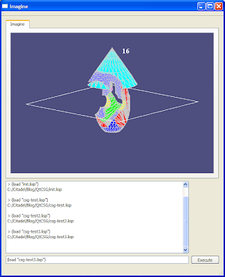
This project is the same as the earlier project, QtImagine except this also features an implementation of "Constructive Solid Geometry" operations that can be performed on 3D models such as difference, union and intersection. The algorithm for performing these operations comes from the UnBBoolean (http://unbboolean.sourceforge.net/) Java CSG implementation.


See the files csg-test.lisp, csg-test2.lisp and csg-test3.lisp for examples on how to use these features. To run them, note that they need to be loaded in order - first csg-test.lisp, then csg-test2.lisp, then finally csg-test3.lisp, since they reference objects that were created by earlier scripts.

Similarly, see init.lisp and live-render.lisp for a live rendering example script.


QtImagine - a skeleton project for live coding using ECL

QtImagine has been updated!

In the process of releasing QtLuaImagine, I cleaned up the code for QtImagine. All lisp code is now run through a (handler-bind) block so that error messages can be captured. What this means is that error messages are displayed in the main window, so no more need to flip between the console and the main window when an error occurs. Also, grey streams have been used to redirect trace output to the main window as well.


This project demonstrates the use of ECL in a Qt project to enable a 3D "live coding" environment.

The system calls the lisp functions (update) and (render) to update and render the frame respectively. These functions can be redefined at runtime at the REPL.

When QtImagine first starts, click the "Execute" button to load an example lisp source file containing example definitions of (update) and (render) which will produce a simple animation. Then, load the source file into your favourite text editor, make some changes, then load your freshly edited source file from the REPL by issuing the load command (load "live-render.lisp") to see the effect of your change instantly. Of course, you can also enter expressions and definitions at the REPL itself. The REPL features a command history.

Scripting simulations with ECL


Download: QtEclSmallSimulations2.zip (Win32 binary)

I've been adding to the program mentioned in a previous post. The circuit simulator and origami crease pattern editor are drivable from the lisp repl, and the verlet physics based paper simulator has been implemented and is manipulated from the repl.

Also, the repl itself features command history.

Here is the list of functions currently available from the repl:

ORIGAMI CREASE EDITOR

origami-start
Initialises origami crease editor with a plain sheet of paper consisting of 1 four sided facet.

origami-end
Clears the origami crease editor.

origami-creasecoords
Takes 4 parameters (x1 y1 x2 y2) representing the 2 endpoints of a crease line.

origami-crease
Takes 2 vertex ids (nodeA nodeB) and uses them as the 2 endpoints of a crease line.

origami-creasepp
Takes 2 vertex ids (nodeA nodeB) and forms the crease from "folding" one vertex on the other. The crease line is the perpendicular bisector.

origami-creasell
Takes 4 vertex ids (l1v1 l1v2 l2v1 l2v2) to describe the endpoints of 2 lines, and forms the crease from "folding" one line onto the other.

origami-fold
Takes 3 vertex ids (nodeF nodeA nodeB) and attempts to fold nodeF around the (nodeA nodeB) line by finding its mirror on the other side. It does the same with connected vertices as necessary.

origami-makeverletpaper
Makes a verlet physics representation of the current crease pattern, so it can be manipulated in the verlet physics environment.

VERLET PHYSICS

verlet-lock
Takes 1 vertex id, and fixes that node in space.

verlet-free
Takes 1 vertex id, and frees that node if it was fixed.

verlet-freeall
Removes all position constraints

verlet-rotate
Takes 4 parameters (nodeF nodeA nodeB angle) and rotates nodeF around the axis defined by nodeA and nodeB using the angle parameter. As the system resolves this attempt to do this rotation, you'll see whether the system currently permits or rejects such a motion.

verlet-numnodes
Returns the number of nodes.

verlet-numstruts
Returns the number of struts.

verlet-show
Not implemented - will show the given node id.

verlet-hide
Not implemented - will hide the given node id.

verlet-showall
Not implemented - will show all node ids.

verlet-hideall
Not implemented - will hide all node ids.

verlet-addfstrut
Not implemented - will add a folding strut, which is the same as the crease struts, but is marked as a folding strut, because it can be removed when a given fold is completed.

verlet-addsstrut
Not implemented - will add a structural strut manually. For facets containing more than 3 edges, structural struts are necessary to keep those facets flat. For the crane model, all facets are triangular, so this isn't necessary yet.

verlet-removefstruts
Not implemented - will remove all folding struts.

verlet-removesstruts
Not implemented - will remove all structural struts.

verlet-autoaddsstruts
Not implemented - will automatically add structural struts where needed for facets containing more than 3 edges.

verlet-satisfy
Not implemented - will allow the user to manually invoke the verlet constraint resolver, rather than having it run all the time.

CIRCUIT SIMULATOR

circuit-AddNode
Takes 2 parameters (x y) and adds a new node at that location.

circuit-AddResistor
Takes 3 parameters (nodeA nodeB resistance) and creates a resistor connecting nodeA and nodeB using the resistance parameter.

circuit-AddVoltage
Takes 3 parameters (nodeA nodeB voltage) and creates a voltage source connecting nodeA and nodeB using the voltage parameter.

circuit-AddCurrent
Takes 3 parameters (nodeA nodeB voltage) and creates a current source connecting nodeA and nodeB using the current parameter.

circuit-SetTweenA
Takes 3 parameters (component x y) and adds a tween vertex on one side of the component. For circuit rendering purposes.

circuit-SetTweenB
Takes 3 parameters (component x y) and adds a tween vertex on one side of the component. For circuit rendering purposes.

circuit-DoLoops
Automatically finds the loops in the circuit. It is necessary to call this once modifications to the circuit are complete for the circuit to be simulated correctly.

circuit-Clear
Clears the current circuit.

circuit-ShowCurrent
Turns on the animated rendering of the current.

circuit-ShowComponents
Turns on rendering of the components.

circuit-ShowNodes
Turns on rendering of the nodes.

circuit-ShowLoops
Turns on rendering of the loops.

circuit-HideCurrent
Turns off the animated rendering of the current.

circuit-HideComponents
Turns off rendering of the components.

circuit-HideNodes
Turns off rendering of the nodes.

circuit-HideLoops
Turns off rendering of the loops.

circuit-Rewire
Takes 3 parameters (componentID nodeFrom nodeTo) and disconnects the component from nodeFrom and connects it to nodeTo.

circuit-DeleteComponent
Takes a componentID as a parameter and deletes it.

circuit-DeleteNode
Takes a nodeID as a parameters and deletes it if there is nothing connected to it.

LIVE RENDERING

ogl-renderon
Turn on live rendering

ogl-renderoff
Turn off live rendering

ogl-drawline
Takes 6 parameters (x1 y1 z1 x2 y2 z2) that describe a 3D line, and renders it. This can only be called from within the paper-render function. Redefine the paper-render function at will at runtime.

OLD TEST FUNCTIONS

myadd
Takes 2 parameters and adds them

myaddlist
Takes a list and adds the numbers in the list.

Screenshots:

Press "Execute" when the program starts to load the script which computes the crane crease pattern:


Having a look at the crease pattern in the pattern editor:


Verlet physics paper manipulation and live rendering: Calling verlet-rotate from the repl to rotate the 4 corner vertices at once, 0.1 degrees at a time (the rotation continues due to momentum), then calling ogl-renderon to turn on live rendering, and modifying the paper-render function live by loading live-render.lisp (the function simul-rotate has been defined for convenience to do the simultaneous rotation):


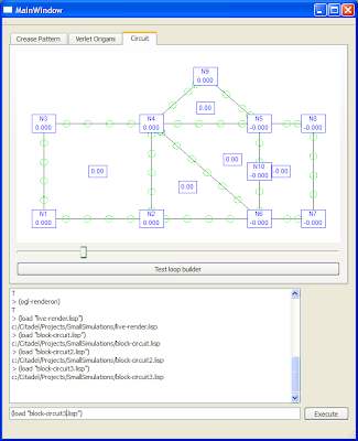
Circuit simulator: Switching to the circuit simulator and loading a circuit (block-circuit.lisp):


Loading the scripts "block-circuit2.lisp" and "block-circuit3.lisp" to modify the circuit:

Embedding a Lisp interpreter into a Qt app


Download: QtEclSmallSimulations2.zip (Win32 binary)

I've been working on a few things these past few months. This includes:
  • A crease pattern generator that can calculate the crease pattern a piece of paper will have based on the sequence of folds applied to it. Conceptualising the paper as a mesh of facets, and determining the operations that can be performed on facets such as splitting was the key to implementing this.
  • A circuit simulator that uses an iterative process to solve the circuit. Since Verlet physics is very successful at applying physical constraints (such as ensuring a point mass is fixed in space, or ensuring two point masses are always a fixed distance apart) using little more than repeatedly pushing objects according to the pressure that each constraint is applying, I thought I would try the same idea with electric circuits and the pressures of KVL and KCL.
When I managed to embed a Lisp interpreter into my app using ECL, I decided this is a suitable thing to tell other people about.
The advantages of scripting using Lisp in this way are numerous and exciting:
  • Its an excellent way to ease into the beauty of Lisp without abandoning my other work.
  • Initially, I can create Lisp bindings that manipulate the interface of the simulation such as adding components to the circuit, or applying specific folds. Doing this, I get loading/saving functionality for free, because my circuit/origami folds/other simulation configuration are defined in a lisp script. Also, I can manipulate my simulation “live” in the lisp repl while the simulation is running.
  • Gradually, I can transfer more and more of the simulation implementation to lisp. Doing so, I can enjoy a real “live coding” environment. I have fluxus to thank for the inspiration.
  • Lisp is a magnificent programming language. Having a Lisp repl in my app means I get a beautiful customisable programming language allowing me to describe a DSL without having to write a single line of parsing code.
The possibilities having a Lisp running in your app are breathtaking. In the past, the only thing that kept me from writing my own language to control my simulations was the mind numbing drudgery of writing parsers. Now, I get all the advantages of a custom language completely for free!
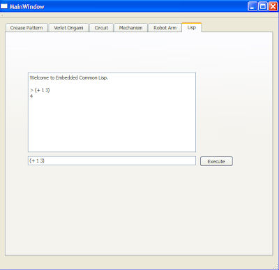
The “Lisp” tab is initially active. It features the Lisp REPL. The only C++ function it is hooked to is myadd – not very exciting from the user's point of view, but VERY exciting for me, since it shows that I can have lisp control the whole show!
Non lisp stuff (will be lispified later):
  • In the “Crease Pattern” tab, press “Push button” repeatedly to see the effect of applying a fold sequence.
  • In the “Circuit” tab, right click a component to select it, and drag the slider to change its parameter (voltage for voltage sources, current for current sources, resistance for resistors.). In between frames, the algorithm runs 100 passes to solve the circuit. You'll notice that the visualisation is inspired by Paul Falstad's circuit simulator – I just wanted to add more interactivity!